Fet Tuned Amplifier – Circuit Diagram and Frequency Response
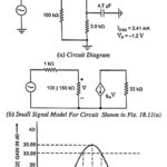
Fet Tuned Amplifier - Circuit Diagram and Frequency Response: Figure 18.11(a) depicts the circuit of an FET tuned amplifier. It uses a first-order JFET model for the 2N 5484 [IDSS…
Single Tuned Amplifier - Circuit Operation and Limitations: The circuit arrangements of a single tuned amplifier are given in Figs. 18.9(a) and 18.9(b). The output may be taken either with…
Phase Splitter Circuit for Push Pull Power Amplifiers (or Phase Inverter): In a push-pull amplifier circuit an input transformer is used to provide the polarity inversion between the two input…
Class AB Push Pull Amplifier - Circuit Diagram, Operation and Drawbacks: The basic circuit of class AB push-pull amplifier is the same as that of class A push-pull amplifier shown…
Class B Push Pull Amplifier - Circuit Diagram, Operation and Derivation: The circuitry for the Class B Push Pull Amplifier operation is the same as that for the class A…
Push Pull Amplifier - Circuit Diagram and its Workings: As we know already that, double-ended or push pull amplifiers makes use of two identical transistors in a single stage. It consists of…
Class D Power Amplifiers - Circuit Diagram, Operation and Applications: Historically, audio amplifiers have been configured as class A, class B or class AB and the art of design is…
Class C Power Amplifiers - Circuit Diagram, Operation and Applications: A class C power amplifiers is biased to operate for less than 180° of the input signal cycle, as shown…