Common Base Circuit Diagram

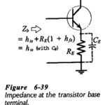
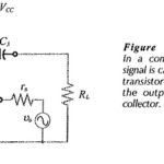
Common Base Circuit Diagram: The Common Base Circuit Diagram (CB) shown in Fig. 6-34 is very similar to a CE circuit, except that the input signal is applied to the…

Continue Reading Common Base Circuit Diagram

Common Collector Circuit Analysis

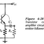
Common Collector Circuit Analysis: In the Common Collector Circuit Analysis (CC) shown in Fig. 6-28 the external load (RL) is capacitor-coupled to the transistor emitter terminal. The circuit uses voltage divider…

Continue Reading Common Collector Circuit Analysis

Common Emitter Amplifier Circuit

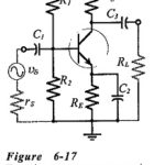
Common Emitter Amplifier Circuit: Consider the Common Emitter Amplifier Circuit circuit shown in Fig. 6-17. When the capacitors are regarded as ac short-circuits, it is seen that the circuit input…

Continue Reading Common Emitter Amplifier Circuit

Bias Circuit Thermal Stability

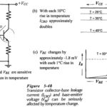
Bias Circuit Thermal Stability: VBE and ICBO Variations - Many transistor circuits are required to operate over a wide temperature range. So, another aspect of bias circuit stability is Bias Circuit…

Continue Reading Bias Circuit Thermal Stability

Interlocking Components in Electrical Drives

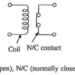
Interlocking Components in Electrical Drives: Sensing of signals required for speed and current control loops. Sequencing and interlocking operations are explained in the previous section, whereas this section discusses components…

Continue Reading Interlocking Components in Electrical Drives

Application of Variable Speed Drives

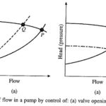
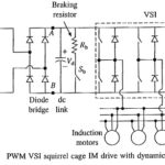
Application of Variable Speed Drives: Several drives are driven at constant speeds by induction or synchronous motors, although operation of Application of Variable Speed Drives could lead to saving of substantial…

Continue Reading Application of Variable Speed Drives