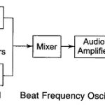
Beat Frequency Oscillator (BFO)
Beat Frequency Oscillator (BFO) | Block Diagram | Working and Limitations: In this Beat Frequency Oscillator, the outputs of two RF oscillators are applied to a square law detector and…
Continue Reading
Beat Frequency Oscillator (BFO)