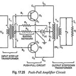
Push Pull Amplifier – Circuit Diagram and its Workings
Push Pull Amplifier - Circuit Diagram and its Workings: As we know already that, double-ended or push pull amplifiers makes use of two identical transistors in a single stage. It consists of…
Class D Power Amplifiers - Circuit Diagram, Operation and Applications: Historically, audio amplifiers have been configured as class A, class B or class AB and the art of design is…
Class B Power Amplifier - Operation and Efficiency derivation: In Class B Power Amplifier operation, the transistor is so biased that zero signal collector current is zero. Hence class B…
Transformer Coupled Class A Power Amplifier: Transformer Coupled Class A Power Amplifier also sometimes referred to as single ended power amplifier. The term "single ended" (denoting only one transistor) is…
Class A Power Amplifiers (Direct Coupled with Resistive Load): A class A power amplifiers is defined as a power amplifier in which output current flows for the entire cycle (360°)…
Various Stages in a Practical Power Amplifier and Block Diagram: Power amplifier is meant to amplify a weak signal until sufficient power is available to operate an output device such…
Classification of Power Amplifiers: Classification of Power Amplifiers are primarily divided into two categories viz. audio power amplifiers and radio power amplifiers. Audio power amplifiers, also called the small signal…
Difference between Voltage Amplifier and Power Amplifier: The Difference between Voltage Amplifier and Power Amplifier are discussed below The primary function of the voltage amplifier is to raise the voltage…