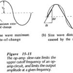
Transistor Voltage and Current

Transistor Voltage and Current: The Transistor Voltage polarities for an npn transistor are shown in Fig. 4-10(a). As well as conventional current direction, the direction of the arrowhead indicates the…

Continue Reading Transistor Voltage and Current

Current Sensing of Electrical Drives

Current Sensing of Electrical Drives: Current Sensing of Electrical Drives is required for the implementation of current limit control, inner current control loop of closed-loop speed control, closed-loop torque control…

Continue Reading Current Sensing of Electrical Drives

Fiber Optic Components and Systems

Fiber Optic Components and Systems: The Fiber Optic Components and Systems can be divided into subgroups, the source, the link, and the detectors. We will now explore the makeup and…

Continue Reading Fiber Optic Components and Systems

Color Picture Tube Working

Color Picture Tube Working: A Color Picture Tube Working requires correct sweep currents, input voltages and drive voltages. Having said this very quickly, it is now a good idea to…

Continue Reading Color Picture Tube Working

Television Horizontal Deflection Circuit

Television Horizontal Deflection Circuit: The function performed by these circuits is exactly the same as already described for the vertical deflection circuits. There are some practical differences. The major one…

Continue Reading Television Horizontal Deflection Circuit

Vertical Deflection Circuit in TV

Vertical Deflection Circuit in TV: The Vertical Deflection Circuit in TV include the vertical oscillator and amplifier for vertical scanning at 60 Hz and a similar horizontal arrangement for scanning…

Continue Reading Vertical Deflection Circuit in TV

Monochrome Television Receiver Block Diagram

Monochrome Television Receiver Block Diagram: Monochrome Television Receiver Block Diagram as shown in Figure 17-9, TV receivers use the superheterodyne principle. There is extensive pulse circuitry, to ensure that the…

Continue Reading Monochrome Television Receiver Block Diagram

CW Doppler Radar Block Diagram

CW Doppler Radar Block Diagram: A simple CW Doppler Radar Block Diagram, such as the one shown in Figure 16-14, sends out continuous sine waves rather than pulses. It uses…

Continue Reading CW Doppler Radar Block Diagram