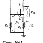
Voltage Divider Bias Circuit
Voltage Divider Bias Circuit: For the self-bias circuit, it was seen that increasing the resistance of RS brings ID(max) and ID(min) closer together, but that increased RS values result in lower ID…
Continue Reading
Voltage Divider Bias Circuit