AF Sine and Square Wave Generator
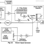
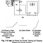
AF Sine and Square Wave Generator: The block diagram of an AF Sine and Square Wave Generator audio oscillator is illustrated in Fig. 8.4. The signal generator is called an…
Modern Laboratory Signal Generator Block Diagram and its Working: Modern Laboratory Signal Generator - To improve the frequency stability, a single master oscillator is optimally designed for the highest frequency…
Standard Signal Generator Block Diagram and Working Principle: A standard signal generator produces known and controllable voltages. It is used as power source for the measurement of gain, signal to…
Oscilloscope Operating Precautions: In addition to the general safety precautions, the following specific precautions should be observed when operating any type of oscilloscope. Most of the Oscilloscope Operating Precautions also…
Attenuators: Attenuators are designed to change the magnitude of the input signal seen at the input stage, while presenting a constant impedance on all ranges at the attenuator input. A…
Setup for Diode Testing in Oscilloscope: Diode Testing in Oscilloscope -The voltage-current characteristics curve of a crystal diode may be observed using the circuit given in Fig. 7.37 (a). In…
What is Electronic Switch in Oscilloscope?: The electronic switch is a device that enables two signals to be displayed simulÂtaneously on the screen by a single gun CRT. The basic…
Dual Trace Oscilloscope: Figure 7.19 (a) shows a block diagram of Dual Trace Oscilloscope. This CRO has a single electron gun whose electron beam is split into two by an…