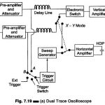
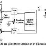
Dual Trace Oscilloscope

Dual Trace Oscilloscope: Figure 7.19 (a) shows a block diagram of Dual Trace Oscilloscope. This CRO has a single electron gun whose electron beam is split into two by an…

Continue Reading Dual Trace Oscilloscope

Delay Line in Triggered Sweep Circuit

Delay Line in Triggered Sweep Circuit: Figure 7.13 shows a Delay Line in Triggered Sweep Circuit. Figure 7.14 indicates the amplitude of the signal wrt time and the relative position…

Continue Reading Delay Line in Triggered Sweep Circuit

Horizontal Deflection System in CRO

Horizontal Deflection System in CRO: The Horizontal Deflection System in CRO consist of a Time Base Generator and an output amplifier. Sweep or Time Base Generator: A continuous sweep CRO…

Continue Reading Horizontal Deflection System in CRO

Block Diagram of CRO

Block Diagram of CRO: The Basic Block Diagram of CRO is shown in Fig.7.5. The ac filament supplies power to the CRT heaters in the Block Diagram of CRO. This…

Continue Reading Block Diagram of CRO

Digital Measurement of Frequency (Mains)

Digital Measurement of Frequency (Mains): Digital Measurement of Frequency (Mains) - The conventional method of measuring the frequency of an electrical signal consists of counting the number of cycles of…

Continue Reading Digital Measurement of Frequency (Mains)

Decade Counter Circuit

Decade Counter Circuit: A Decade Counter Circuit is of flip-flops (F/Fs) in cascade, which counts in the base 10 (decimal number system). This means that there is a sequence of…

Continue Reading Decade Counter Circuit