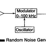
Random Noise Generator Block Diagram and its Working
Random Noise Generator Block Diagram and its Working: A simplified Random Noise Generator Block Diagram used in the audio frequency range is shown in Fig. 8.8. The instrument offers the…
Continue Reading
Random Noise Generator Block Diagram and its Working