Digital Fourier Analyzer
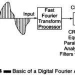
Digital Fourier Analyzer: The basic principle of a Digital Fourier Analyzer is shown in Fig. 9.14. The Digital Fourier Analyzer converts the analogue waveform over time period T into N…
Spectrum Analyzer Block Diagram: Spectrum Analyzer Block Diagram - The most common way of observing signals is to display them on an oscilloscope, with time as the X-axis (i.e. amplitude…
Heterodyne Wave Analyzer: Wave analyzers are useful for measurement in the audio frequency range only. For measurements in the RF range and above (MHz range), an ordinary wave analyzer cannot…
What is Wave Analyzer?: It can be shown mathematically that any complex waveform is made up of a fundamental and its harmonics. It is often desired to measure the amplitude…
Beat Frequency Oscillator (BFO) | Block Diagram | Working and Limitations: In this Beat Frequency Oscillator, the outputs of two RF oscillators are applied to a square law detector and…
Marker Generator Block Diagram: Marker Generator - The sweep generator provides a visual display of the characteristics of the circuit or amplifier, but this is inadequate because it does not…
Pulse and Square Wave Generator Block Diagram (Laboratory Type): Pulse and Square Wave Generator are used as measuring devices in combination with a CRO. They provide both quantitative and qualitative…
Modern Laboratory Signal Generator Block Diagram and its Working: Modern Laboratory Signal Generator - To improve the frequency stability, a single master oscillator is optimally designed for the highest frequency…