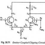
Emitter Coupled Clipper Circuit
Emitter Coupled Clipper Circuit: An emitter coupled clipper using two transistors is shown in Fig. 30.71. It is a two level clipper in which the input is applied to the…
Continue Reading
Emitter Coupled Clipper Circuit