Biasing Transistor Switching Circuits
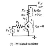
Biasing Transistor Switching Circuits: Direct-Coupled Switching Circuit - When a transistor is used as a Biasing Transistor Switching Circuits, it is either biased off to IC = 0, or biased…
DC Load Line of BJT Biasing Circuit: The DC Load Line of BJT Biasing Circuit is a straight line drawn on the transistor output characteristics. For a common-emitter (CE) circuit,…
Amplification in Transistor: Current Amplification in Transistor - We already know that a transistor can be used for current amplification. A small change in the base current (ΔIB) produces a large…
Ward Leonard Method of Speed Control: Known after the name of its inventor Ward Leonard Method of Speed Control (1891), it consists of a separately excited generator feeding the dc…
Fiber Optic Components and Systems: The Fiber Optic Components and Systems can be divided into subgroups, the source, the link, and the detectors. We will now explore the makeup and…
Television System Articles: Introduction to Television: Introduction to Television tells first thing of seeing at a distance. To be successful, a television system may be required to reproduce faithfully: The…
Color Television Receiver Block Diagram: Figure 17-25 shows the block diagram of a Color Television Receiver Block Diagram, but for simplicity the circuits shown in Figure 17-23 are omitted. Interconnection…
Color Picture Tube Working: A Color Picture Tube Working requires correct sweep currents, input voltages and drive voltages. Having said this very quickly, it is now a good idea to…