Hays Bridge Circuit
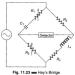
Hays Bridge Circuit: Hays Bridge Circuit, shown in Fig. 11.23, differs from Maxwell's bridge by having a resistance R1 in series with a standard capacitor C1 instead of a parallel.…
Continue Reading
Hays Bridge Circuit
Hays Bridge Circuit: Hays Bridge Circuit, shown in Fig. 11.23, differs from Maxwell's bridge by having a resistance R1 in series with a standard capacitor C1 instead of a parallel.…
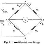
Wheatstone Bridge Diagram: A Wheatstone Bridge diagram in its simplest form consists of a network of four resistance arms forming a closed circuit, with a dc source of current applied…
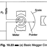
Megger Circuit Diagram: Another common method of measuring resistances above 50 M Ω is the Megger Circuit Diagram (megaohmmeter) shown in Fig. 10.23(a). This instrument is used to measure very…
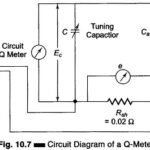
Q Meter: The overall efficiency of coils and capacitors intended for RF applications is best evaluated using the Q value. The Q Meter is used to measure some electrical properties…
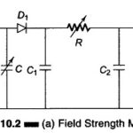
Field Strength Meter (Transistor) Circuit: The Field Strength Meter is used to measure the radiation intensity from a transmitting antenna at a given location. With its own small antenna, it…
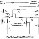
Output Power Meter Working Principle: The Output Power Meter Working Principle is designed to directly measure the output power in an arbitrary load. The instrument provides a set of resistive…
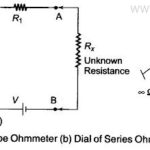
Series Type Ohmmeter: Series Type Ohmmeter - A D' Arsonval movement is connected in series with a resistance R1 and a battery which is connected to a pair of terminals…
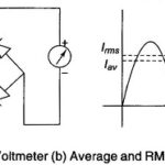
AC Voltmeter using Rectifiers: AC Voltmeter using Rectifiers - Rectifier type instruments generally use a PMMC movement along with a rectifier arrangement. Silicon diodes are preferred because of their low…