JFET Characteristics

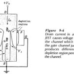
JFET Characteristics: An n-channel JFET Characteristics block representation is shown in Fig. 9-6. With a drain-source voltage applied as illustrated, ID flows in the direction shown producing voltage drops along…

Continue Reading JFET Characteristics

Biasing Transistor Switching Circuits

Biasing Transistor Switching Circuits: Direct-Coupled Switching Circuit - When a transistor is used as a Biasing Transistor Switching Circuits, it is either biased off to IC = 0, or biased…

Continue Reading Biasing Transistor Switching Circuits

DC Load Line of BJT Biasing Circuit

DC Load Line of BJT Biasing Circuit: The DC Load Line of BJT Biasing Circuit is a straight line drawn on the transistor output characteristics. For a common-emitter (CE) circuit,…

Continue Reading DC Load Line of BJT Biasing Circuit

Transistor Testing Circuit

Transistor Testing Circuit: In-Circuit Testing - A quick test to check if a transistor is operational can be performed while the device is still connected in a circuit. Consider Fig.…

Continue Reading Transistor Testing Circuit

Testing of Semiconductor Diode

Testing of Semiconductor Diode: There are Several methods are available for Testing of Semiconductor Diode, namely, Ohmmeter Tests: One of the simplest and quickest tests can be made using an ohmmeter…

Continue Reading Testing of Semiconductor Diode

Switched Reluctance Motor

Switched Reluctance Motor: The switched reluctance motor (SRM) has both salient pole stator and rotor, like variable stepper motor, but they are designed for different applications, and therefore, with different…

Continue Reading Switched Reluctance Motor

High Frequency Limitations

High Frequency Limitations: As stated, transistors suffer from High Frequency Limitations. These are of a twofold nature. On the one hand, there are the same difficulties as those encountered with…

Continue Reading High Frequency Limitations