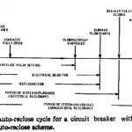
Auto Reclosing Scheme
Auto Reclosing Scheme: Auto Reclosing Scheme - It is well realized that the transient faults which are most frequent in occurrence do no permanent damage to the system as they…
Continue Reading
Auto Reclosing Scheme
Auto Reclosing Scheme: Auto Reclosing Scheme - It is well realized that the transient faults which are most frequent in occurrence do no permanent damage to the system as they…
Transformer Protection Types: Nature of Transformer Faults: Power transformers, being static, totally enclosed and oil immersed develop faults only rarely but the consequences of even a rare fault may be…
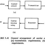
Carrier Pilot Protection and Microwave Pilot Protection: The problem of providing economically an auxiliary channel by means of pilots for long lines directed attention to carrier techniques. In this case…
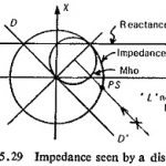
Power Swings in Power System Protection: The impedance measured or seen by a distance relay during normal load is shown in Fig. (5.29). Normally this would be outside the tripping…
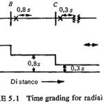
Overcurrent Protection of Feeders: Overcurrent relays offer the cheapest and the simplest protection for lines. The maximum load currents must be known to determine whether the ratio of the minimum…
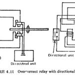
Directional Relays: Selective protection cannot be achieved with time graded overcurrent protection systems in ring or loop systems as well as in radial circuits with two end power supply. A…
Instantaneous Overcurrent Relays: If the relay operates instantly without any intentional time delay, this characteristic can generally be satisfied by a relay of the non-polarized attracted armature type. This relay…
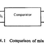
Comparator Equation in Power System Protection: Comparator Equation in Power System Protection - Taking a very general case to cover the complete range of conventional relay characteristics, let S1 and S2…