Linear Resistance Damping
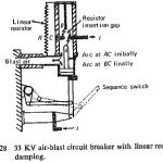
Linear Resistance Damping: By introducing a linear resistance across the circuit breaker during interruption, the restriking transients are damped. Provision has to be made for subsequent interruption of the resistance…
Continue Reading
Linear Resistance Damping