Frequency Compensation Methods

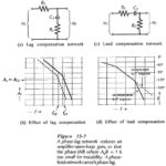
Frequency Compensation Methods: Phase-Lag and Phase-Lead Compensation - Lag compensation and lead compensation are two Frequency Compensation Methods often employed to stabilize op-amp circuits. The phase-lag network in Fig. 15-7(a)…

Continue Reading Frequency Compensation Methods

Schmitt Trigger Circuit Diagram

Schmitt Trigger Circuit Diagram: Inverting Schmitt Trigger - A Schmitt Trigger Circuit Diagram is a fast-operating voltage level detector. When the input voltage arrives at a level determined by the…

Continue Reading Schmitt Trigger Circuit Diagram

Voltage Level Detectors

Voltage Level Detectors: Voltage Level Detectors - Operational amplifiers are often used in circuits in which the output is switched between the positive and negative saturation voltages, +Vo(sat) and -+Vo(sat). The…

Continue Reading Voltage Level Detectors

Voltage Follower Circuit Diagram

Voltage Follower Circuit Diagram: Direct-Coupled Voltage Follower - The IC operational amplifier can be employed for an infinite variety of applications. The very simplest application is the direct-coupled Voltage Follower…

Continue Reading Voltage Follower Circuit Diagram

Biasing Bipolar Op Amp Circuit

Biasing Bipolar Op Amp Circuit: Biasing Bipolar Op Amp Circuit - Like other electronic devices, operational amplifiers must be correctly biased if they are to function properly. As already discussed,…

Continue Reading Biasing Bipolar Op Amp Circuit

Emitter Current Feedback Circuit

Emitter Current Feedback Circuit: Emitter Current Feedback Circuit is produced by connecting an unbypassed resistor in series with the emitter terminal of a transistor, as shown in Fig. 13-24(a). The…

Continue Reading Emitter Current Feedback Circuit

Direct Coupled Circuits

Direct Coupled Circuits: For economy, the number of components used in any circuit should be kept to a minimum. The use of direct coupling between stages is one way of…

Continue Reading Direct Coupled Circuits

Common Source Circuit Analysis

Common Source Circuit Analysis: A FET Common Source Circuit Analysis is shown in Fig. 11-­6. With the capacitors treated as ac short-circuits, the circuit input terminals are the gate and…

Continue Reading Common Source Circuit Analysis