UJT as Over Voltage Detector Circuit Diagram
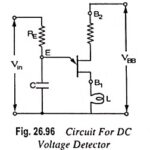
UJT as Over Voltage Detector Circuit Diagram: UJT as Over Voltage Detector Circuit Diagram - A simple dc overvoltage detector circuit is given in Fig. 26.96. It operates on the…
UJT Relaxation Oscillator - Circuit Diagram and its Workings: UJT Relaxation Oscillator - The relaxation oscillator shown in Fig. 26.94 (a) consists of UJT and a capacitor C which is…
UJT Triggering of SCR Working Principle: UJT Triggering of SCR Working Principle - One common application of the unijunction transistor is the triggering of the other devices such as the…
Silicon Controlled Switch (SCS) - Symbol, Operation, Advantages and Application: Silicon controlled switch (SCS), like the SCR, is a unilateral, four layer, three junction P-N-P-N silicon device with four electrodes…
SCR as Half Wave Rectifier Circuit Diagram: SCRs are very useful in ac circuits where they may serve as rectifiers whose output current can be controlled by controlling the gate…
Linear Diode Detector or Envelope Detector: Diode detection is called the envelope detection as it recovers the audio frequency signal envelope from the composite signal. Diode detector is also called…
Generation of DSBSC Signal using Balanced and Ring Modulator: DSBSC signal can be obtained by simply multiplying the modulating signal with the carrier signal. By simple multiplication of Vc sin ωct…
Emitter Modulation - Circuit Diagram and its Operation: The circuit for emitter modulation is shown in Fig. 22.29. It is essentially a CE amplifier. The carrier signal from a crystal…