FET Configurations
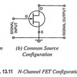
FET Configurations: FETs (JFETs and MOSFETs) have three configurations just as BJTs have. The three FET Configurations—the common gate, common source, and common drain configuration have been given in Fig.…
Photodarlington Working: The Photodarlington Working shown in (Fig. 20-33) consists of a phototransistor connected in Darlington arrangement with another transistor. This device is capable of producing much higher output currents…
FET Biasing Articles: DC Load Line for FET: The DC Load Line for FET circuit is drawn on the device output characteristics (or drain characteristics) in exactly the same way…
Field Effect Transistors Articles: Junction Field Effect Transistor Theory: n-Channel JFET – The operating principle of an n-channel Junction Field Effect Transistor Theory (JFET) is illustrated by the block representation…
BIFET Amplifier: BJT-FET Considerations : Two-stage BJT circuits usually have relatively low input impedances. To increase Zi, a field effect transistor may be used as the first stage. Circuits which…
Frequency Response of FET Amplifier: Low-Frequency Response - The low Frequency Response of FET Amplifier circuits is determined by exactly the same considerations as for BJT circuits. The lower cutoff…
Common Source Circuit Analysis: A FET Common Source Circuit Analysis is shown in Fig. 11-Â6. With the capacitors treated as ac short-circuits, the circuit input terminals are the gate and…
FET Equivalent Circuit Model: The complete FET Equivalent Circuit Model is shown in Fig. 11-5(a). It is seen that tilt source terminal is common to both input and out, so…