Vacuum Triode, Construction and Working

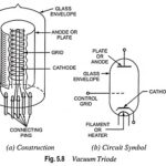
Vacuum Triode, Construction and Working: Construction of Vacuum Triode - The construction and the schematic symbol used for a vacuum triode are illustrated in Fig. 5.8. It, as the name…

Continue Reading Vacuum Triode, Construction and Working

Measurement of Electrical Quantities

Measurement of Electrical Quantities: Measurement of electrical quantities which includes Measurement of Voltage Measurement of Current Frequency Measurement Phase-Angle Measurement Power-Factor Measurement Impedance Measurement VA Measurement Power Measurement VAR Measurement…

Continue Reading Measurement of Electrical Quantities

Solid State Modulator/Demodulator Circuit

Solid State Modulator/Demodulator Circuit: A solid state modulator/demodulator circuit is shown in Fig. 14.41. The transĀ­former T is driven by an ac source and couples each secondary connected to the…

Continue Reading Solid State Modulator/Demodulator Circuit

DC Circuit Breaker

DC Circuit Breaker: Light duty DC Circuit Breaker have been in use since long. However, with the latest developments in HVDC transmission there would naturally be the necessity of the…

Continue Reading DC Circuit Breaker

Coincidence Type Phase Comparator

Coincidence Type Phase Comparator: The basic concept of phase comparison is simpler in that it is possible to deal with signals of equal strength whose coincidence (or noncoinecidence) is readily…

Continue Reading Coincidence Type Phase Comparator

Static Amplitude Comparator

Static Amplitude Comparator: If the two input signals are S1 and S2 the amplitude comparator gives positive (yes) output only if S2/S1Ā ā‰¤ K (Fig. (11.1)), S1 is the operating quantity…

Continue Reading Static Amplitude Comparator

Motor Protection

Motor Protection: Motor Protection - There is a wide range of motors in existence for various purposes. However, the fundamental problems affecting the choice of protection are independent of the…

Continue Reading Motor Protection

Diode Applications Articles

Diode Applications Articles: Half Wave Rectifier Circuit: A basic diode Half Wave Rectifier Circuit is shown in Fig. 3-1(a). An alternating input voltage is applied to a single diode connected…

Continue Reading Diode Applications Articles