Elemental Semiconductor Materials
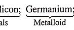
Elemental Semiconductor Materials: Group IV includes five elements viz., Carbon (C), Silicon (Si), Germanium (Ge), Tin (Sn) and lead (Pb). The elements of this subgroup show marked similarity as well…
Continue Reading
Elemental Semiconductor Materials