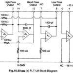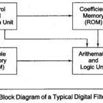
Block Diagram of a Digital Filtering Processor
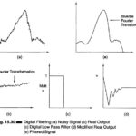
Block Diagram of a Digital Filtering Processor: The implementation of any digital filtering consists of a series of multiplications of samples of the input and/or output signals by constants, and…
Continue Reading
Block Diagram of a Digital Filtering Processor