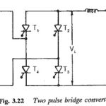
Two pulse bridge converter
Two pulse bridge converter: A two pulse bridge converter is achieved as shown in Fig. 3.22 from two midpoint converters. They are connected in series on the dc side and…
Continue Reading
Two pulse bridge converter
Two pulse bridge converter: A two pulse bridge converter is achieved as shown in Fig. 3.22 from two midpoint converters. They are connected in series on the dc side and…
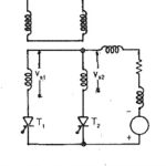
Two pulse mid point converter: Two pulse mid point converter are, in general, single phase converters. The pulse number of the converter indicates the frequency of the ripple voltage superimposing…
Phase Controlled Line Commutated Converters: In these Phase Controlled Line Commutated Converters, the commutation voltage, i.e. the voltage required to transfer current from one thyristor to the other, is provided…
Electric Converter: Electric Converter - The speed of a dc motor can be varied by varying the armature voltage or the field current, for which a variable dc supply is…
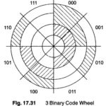
Electromechanical AD Converter: Another area of application in which Electromechanical AD Converter is very important, involves the translation of the angular position of a shaft into digital information. (A very…
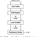
DA Converter Working Principle: The resistive divider or ladder can be used as the basis for a DA Converter Working Principle. It is in the resistive network that the actual…
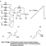
Weighted Converter Using Transistor Switches (Current Switch): Figure 17.19 (a) shows a circuit diagram of a weighted converter, using transistor switches. When the D bit is high (logic 1), it…
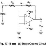
Digital to Analog Converter Circuit Diagram: The basic Digital to Analog Converter Circuit Diagram using Op Amp is shown in Fig. 17.18(a). The input signal is applied to the inverting…