Radio Frequency Modulation
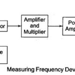
Radio Frequency Modulation: Radio Frequency Modulation - The simplest method of measuring frequency deviation utilises an FM receiver with a BFO as the measuring instrument. The only coupling used is…
Continue Reading
Radio Frequency Modulation