TRIAC Control Circuit Diagram

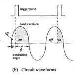
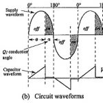
TRIAC Control Circuit Diagram: A TRIAC Control Circuit Diagram that allows approximately 180° of phase control is shown in Fig. 19-27(a). The waveforms in Fig. 19-27(b) illustrate the circuit operation.…

Continue Reading TRIAC Control Circuit Diagram

SCR Applications Circuits

SCR Applications Circuits: SCR Applications Circuits : An SCR circuit is stable when it operates correctly: switching on and off only at the desired instants. Unwanted triggering (also called false…

Continue Reading SCR Applications Circuits

SCR Control Circuit Diagram

SCR Control Circuit Diagram: Pulse Control - The simplest of SCR Control Circuit Diagram is shown in Fig. 19-8(a). If SCR1 was an ordinary rectifier, the ac supply voltage would…

Continue Reading SCR Control Circuit Diagram

Bridge Tied Load Amplifier

Bridge Tied Load Amplifier: All of the power amplifiers already discussed have been single-ended (SE): meaning that they provide power to a load that has one terminal grounded and the…

Continue Reading Bridge Tied Load Amplifier

Audio Power Amplifier using IC Amplifier Driver

Audio Power Amplifier using IC Amplifier Driver: The LM391 integrated circuit Audio Power Amplifier using IC Amplifier Driver contains amplification and driver stages for controlling an externally-connected Class-AB output stage…

Continue Reading Audio Power Amplifier using IC Amplifier Driver

BJT Power Amplifier with Op Amp Driver

BJT Power Amplifier with Op Amp Driver: BJT Power Amplifier with Op Amp Driver Circuit Operation - The Class-AB power shown in Fig. 18-39 uses an operational amplifier (A1) for…

Continue Reading BJT Power Amplifier with Op Amp Driver

Operational Amplifier Frequency Response Articles

Operational Amplifier Frequency Response Articles: Operational Amplifier Circuit Stability: Loop Gain and Loop Phase Shift – Consider the inverting amplifier circuit and waveforms in Fig. 15-­1(a). The signal voltage voltage…

Continue Reading Operational Amplifier Frequency Response Articles