Circuit Stability Precautions
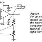
Circuit Stability Precautions: Power Supply Decoupling - Feedback along supply lines is another source of op-amp circuit instability. This can be minimized by connecting 0.01 μF high-frequency capacitors from each…
Continue Reading
Circuit Stability Precautions