Modern Laboratory Signal Generator Block Diagram and its Working
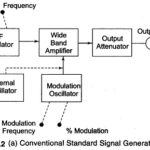
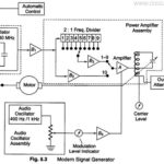
Modern Laboratory Signal Generator Block Diagram and its Working: Modern Laboratory Signal Generator - To improve the frequency stability, a single master oscillator is optimally designed for the highest frequency…
Continue Reading
Modern Laboratory Signal Generator Block Diagram and its Working