Block Diagram of Oscilloscope
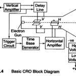
Block Diagram of Oscilloscope: The major Block Diagram of Oscilloscope shown in Fig. 7.4, of a general purpose CRO, is as follows: CRT Vertical amplifier Delay line Time base Horizontal…
What is the Principle of Sweep Generator?: Principle of Sweep Generator : The amplitude of a voltage may be directly measured on a calibrated viewing screen from the length of…
Digital Phase Meter Block Diagram and Working Principle: Digital Phase Meter - The simplest technique to measure the phase difference between two signals employs two flip-flops. The signals to be…
Automation in Digital Instruments: Automation in Digital Instruments - One of the advantages of digital multimeters is their ease of operation. The reading is easy to take and does not…
Working Principle of Digital Multimeter: Analog meters require no power supply, they give a better visual indication of changes and suffer less from electric noise and isolation problems. These meters…
Continuous Balance DVM: Continuous Balance DVM - The basic block diagram of a servo balancing potentiometer type DVM is shown in Fig. 5.15. The input voltage is applied to one…
Considerations in Choosing an Analog Voltmeter: Considerations in Choosing an Analog Voltmeter has the following factors are to be considered. 1. Input Impedance The input impedance or resistance of the…
True RMS Voltmeter: True RMS Voltmeter - Complex waveform are most accurately measured with an rms voltmeter. This instrument produces a meter indication by sensing waveform heating power, which is…