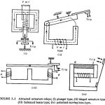
SCR Control Circuit Diagram
SCR Control Circuit Diagram: Pulse Control - The simplest of SCR Control Circuit Diagram is shown in Fig. 19-8(a). If SCR1 was an ordinary rectifier, the ac supply voltage would…
Bridge Tied Load Amplifier: All of the power amplifiers already discussed have been single-ended (SE): meaning that they provide power to a load that has one terminal grounded and the…
Audio Power Amplifier using IC Amplifier Driver: The LM391 integrated circuit Audio Power Amplifier using IC Amplifier Driver contains amplification and driver stages for controlling an externally-connected Class-AB output stage…
Common Source Power Amplifier Using an Op Amp Driver Stage: Basic Circuit Operation - The Class-AB MOSFET Power Amplifier with OP Amp Driver Stage circuit in Fig. 18-45(a) consists of…
BJT Power Amplifier with Op Amp Driver: BJT Power Amplifier with Op Amp Driver Circuit Operation - The Class-AB power shown in Fig. 18-39 uses an operational amplifier (A1) for…
Operational Amplifier Frequency Response Articles: Operational Amplifier Circuit Stability: Loop Gain and Loop Phase Shift – Consider the inverting amplifier circuit and waveforms in Fig. 15-Â1(a). The signal voltage voltage…
FET Biasing Articles: DC Load Line for FET: The DC Load Line for FET circuit is drawn on the device output characteristics (or drain characteristics) in exactly the same way…
Semiconductor Diodes Articles: PN Junction Diode Working Principle: A PN Junction Diode Working Principle explains about the ability to permit substantial current flow when forward-biased, and to block current when…