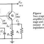
Two Stage Direct Coupled BJT Amplifier Circuit
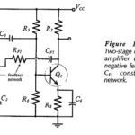
Two Stage Direct Coupled BJT Amplifier Circuit: The Two Stage Direct Coupled BJT Amplifier Circuit in Fig. 13-17 is reproduced from Fig. 12-22, and modified to include feedback components RF1 and…
Continue Reading
Two Stage Direct Coupled BJT Amplifier Circuit