Pulse Code Modulation

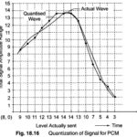
Pulse Code Modulation(PCM): Pulse Code Modulation(PCM) is different from the other forms of pulse modulation studied so far, PCM also uses sampling techniques, but it differs from the others in…

Continue Reading Pulse Code Modulation

Pulse Width Modulation

Pulse Width Modulation(PWM): Pulse width modulation of PTM is also often called Pulse Duration Modulation (PDM). In this system, shown in Fig. 18.8, we have a fixed amplitude and starting…

Continue Reading Pulse Width Modulation

Pulse Time Modulation

Pulse Time Modulation(PTM): In Pulse Time Modulation the signal is sampled in the same way as in PAM, but the pulses indicating instantaneous sample amplitudes have a constant amplitude themselves.…

Continue Reading Pulse Time Modulation

Pulse Amplitude Modulation

Pulse Amplitude Modulation(PAM): Pulse Amplitude Modulation(PAM) is the simplest form of Pulse Modulation. It is shown in Fig. 18.7. PAM is a pulse modulation system in which the signal is…

Continue Reading Pulse Amplitude Modulation

CCIF Intermodulation Distortion

CCIF Intermodulation Distortion: In the second method of carrying out an CCIF Intermodulation Distortion test, the two test signals used have equal amplitude, and relatively high but slightly different frequencies.…

Continue Reading CCIF Intermodulation Distortion

Nonlinear Distortion Measurements

Nonlinear Distortion Measurements: One of the methods of Nonlinear Distortion Measurements consists of simulta­neously applying two sinusoidal voltages of different frequencies to the amplifier input and observing the sum, difference…

Continue Reading Nonlinear Distortion Measurements

Frequency Modulation Recording

Frequency Modulation Recording: When a more accurate response to dc voltages is required, an Frequency Modulation Recording system is generally used. In this FM system, the input signal is used…

Continue Reading Frequency Modulation Recording

Spectrum Analyzer Block Diagram

Spectrum Analyzer Block Diagram: Spectrum Analyzer Block Diagram - The most common way of observing signals is to display them on an oscilloscope, with time as the X-axis (i.e. amplitude…

Continue Reading Spectrum Analyzer Block Diagram