Common Base Circuit Diagram
Common Base Circuit Diagram: The Common Base Circuit Diagram (CB) shown in Fig. 6-34 is very similar to a CE circuit, except that the input signal is applied to the…
Continue Reading
Common Base Circuit Diagram
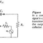
Common Base Circuit Diagram: The Common Base Circuit Diagram (CB) shown in Fig. 6-34 is very similar to a CE circuit, except that the input signal is applied to the…
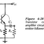
Common Collector Circuit Analysis: In the Common Collector Circuit Analysis (CC) shown in Fig. 6-28 the external load (RL) is capacitor-coupled to the transistor emitter terminal. The circuit uses voltage divider…
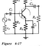
Common Emitter Amplifier Circuit: Consider the Common Emitter Amplifier Circuit circuit shown in Fig. 6-17. When the capacitors are regarded as ac short-circuits, it is seen that the circuit input…
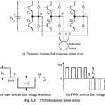
Voltage Source Inverter Control of Induction Motor: Variable frequency and variable voltage supply for induction motor control can be obtained either from a voltage sourve inverter (VSI) or a cycloconverter.…
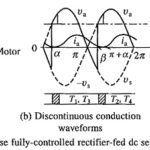
Single Phase Fully Controlled Rectifier Control of DC Motor: The Single Phase Fully Controlled Rectifier Control of DC Motor is shown in Fig. 5.26(a). Motor is shown by its equivalent…
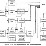
Color TV Transmission: Having discussed the manner of indicating luminance and the two components of chrominance in Color TV Transmission, it is now necessary to investigate how they may be,…
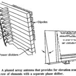
Phased Array Radars: Phased Array Radars - Introduction With some notable exceptions, the vast majority of radars have to cover an area in searching and/or tracking, rather than always being…
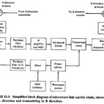
Microwave Link in Electronic Communication: A Microwave Link in Electronic Communication performs the same functions as a copper or optic fiber cable, but in a different manner, by using point-to-point…