Non Inverting Amplifier Theory
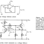
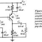
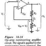
Non Inverting Amplifier Theory: Direct-Coupled Noninverting Amplifier - The Non Inverting Amplifier Theory circuit in Fig. 14-14 behaves similarly to a voltage follower circuit with one major difference. Instead of…
Continue Reading
Non Inverting Amplifier Theory