JFET Bias Circuit Design
JFET Bias Circuit Design: Design Approach - Design of JFET Bias Circuit Design is just as simple as design of BJT bias circuits. One major difference is that FET circuit…
Continue Reading
JFET Bias Circuit Design
JFET Bias Circuit Design: Design Approach - Design of JFET Bias Circuit Design is just as simple as design of BJT bias circuits. One major difference is that FET circuit…
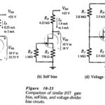
Basic JFET Biasing Circuits Comparison: The Basic JFET Biasing Circuits Comparison (gate bias, self-bias, and voltage divider bias) are similar in performance to the three basic BLIP bias circuits, (base…
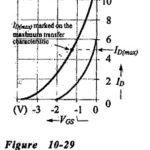
Voltage Divider Bias Circuit: For the self-bias circuit, it was seen that increasing the resistance of RS brings ID(max) and ID(min) closer together, but that increased RS values result in lower ID…
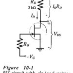
DC Load Line for FET: The DC Load Line for FET circuit is drawn on the device output characteristics (or drain characteristics) in exactly the same way as for a…
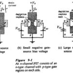
Junction Field Effect Transistor Theory: n-Channel JFET - The operating principle of an n-channel Junction Field Effect Transistor Theory (JFET) is illustrated by the block representation in Fig. 9-1(a). A…
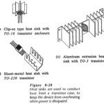
Heat Sink in Transistor: When power is dissipated in a transistor, the heat generated must flow from the collector-base junction to the case, and then to the surrounding atmosphere. When…
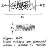
Transistor Circuit Noise: Unwanted signals at the output of an electronics system are termed noise. The noise amplitude may be large enough to severely distort, or completely swamp, the wanted…
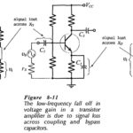
High Frequency Analysis of BJT: Coupling and Bypass Capacitor Effects - Consider the typical High Frequency Analysis of BJT illustrated in Fig. 8-5. As discussed, the amplifier voltage gain is…