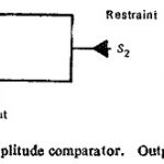
Coincidence Type Phase Comparator
Coincidence Type Phase Comparator: The basic concept of phase comparison is simpler in that it is possible to deal with signals of equal strength whose coincidence (or noncoinecidence) is readily…
Continue Reading
Coincidence Type Phase Comparator