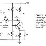
Voltage Divider Bias Circuit

Voltage Divider Bias Circuit: For the self-bias circuit, it was seen that increasing the resistance of RS brings ID(max) and ID(min) closer together, but that increased RS values result in lower ID…

Continue Reading Voltage Divider Bias Circuit

High Frequency Analysis of BJT

High Frequency Analysis of BJT: Coupling and Bypass Capacitor Effects - Consider the typical High Frequency Analysis of BJT illustrated in Fig. 8-5. As discussed, the amplifier voltage gain is…

Continue Reading High Frequency Analysis of BJT

Transistor Voltage and Current

Transistor Voltage and Current: The Transistor Voltage polarities for an npn transistor are shown in Fig. 4-10(a). As well as conventional current direction, the direction of the arrowhead indicates the…

Continue Reading Transistor Voltage and Current

Voltage Doubler Circuit

Voltage Doubler Circuit: A Voltage Doubler Circuit produces an output voltage which is approximately double the peak voltage of the input waveform. Consideration of the voltage doubler circuit diagram in…

Continue Reading Voltage Doubler Circuit

Stator Voltage Control of Induction Motor

Stator Voltage Control of Induction Motor: By reducing Stator Voltage Control of Induction Motor, speed of a high-slip induction motor can be reduced by an amount which is sufficient for…

Continue Reading Stator Voltage Control of Induction Motor

Armature Voltage Control using Transformer

Armature Voltage Control using Transformer: Variable voltage for the dc motor control can also be obtained by either using an auto-transformer or a Armature Voltage Control using Transformer with tappings…

Continue Reading Armature Voltage Control using Transformer