BJT Power Amplifier with Op Amp Driver
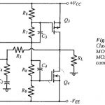
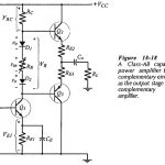
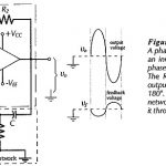
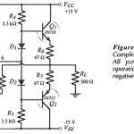
BJT Power Amplifier with Op Amp Driver: BJT Power Amplifier with Op Amp Driver Circuit Operation - The Class-AB power shown in Fig. 18-39 uses an operational amplifier (A1) for…
Small Signal Amplifiers Articles: Single Stage Common Emitter Amplifier Circuit: Specification – Bias circuit design for the Single Stage Common Emitter Amplifier Circuit in shown in Fig. 12-1 and ac…
Complementary MOSFET Common Source Power Amplifier: Advantages of MOSFETs: Complementary MOSFET Common Source Power Amplifier have several advantages over power BJTs for large signal amplifier applications. One of the most…
Quasi Complementary Output Stage: The Quasi Complementary Output Stage was originally developed because complementary high-power transistors were not readily available. Despite the fact that such transistors are now available, the…
Capacitor Coupled Class AB Output Stage: The basic circuit of a Class-AB amplifier using a complementary emitter follower output stage and a Capacitor Coupled Class AB Output Stage load is…
RC Phase Shift Oscillator Circuit Diagram: Figure 16-1 shows the RC Phase Shift Oscillator Circuit Diagram, which consists of an inverting amplifier and an RC phase-shifting network. The amplifier phase-shifts…
Integrated Circuit Operational Amplifier: Circuit Symbol and Packages - Figure 14-1(a) shows the triangular circuit symbol for an Integrated Circuit Operational Amplifier (op-amp). As illustrated, there are two input terminals,…
Two Stage Differential Amplifier with Negative Feedback: The circuit shown in Fig. 13-20 has a Two Stage Differential Amplifier with Negative Feedback with npn BJTs, and a direct-coupled pnp transistor…