Generalized FET Amplifier Circuit
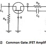
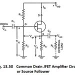
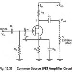
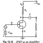
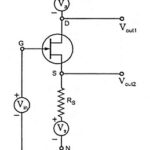
Generalized FET Amplifier Circuit: The analysis of a common source amplifier with a source resistance RS, a common gate amplifier and a common drain amplifier at low frequencies may be…
Common Gate JFET Amplifier and its AC Equivalent Circuit: The circuit of a simple Common Gate JFET Amplifier is shown in Fig. 13.53 and its ac equivalent circuit is shown…
Common Drain JFET Amplifier or Source Follower: In the Common Drain JFET Amplifier circuit (also called the source follower), the output voltage is developed across source resistor RS. External load…
Common Source JFET Amplifier with AC Equivalent Circuit: The Common Source JFET Amplifier Circuit configuration is the most widely employed configuration. It is because this configuration provides high input impedance,…
FET Biasing Methods - Fixed Bias, Self Bias, Potential Divider Bias and Current Source Bias: Unlike BJTs, thermal runaway does not occur with FETs. However, the wide differences in maximum…
JFET as an Amplifier: One of the applications of JFET as an Amplifier of input signal. In FET the weak signal is applied between gate and source and an amplified…
What is Current Conveyors (CCs)? Current conveyors (CCs) were first introduced by Smith and Sedra and have been used in a variety of electronic applications. The CC is a three-port…
OTA Voltage Amplifier Circuit Diagram: A basic OTA voltage amplifier circuit diagram is shown in Fig. 41.4. At room temperature (T = 300 K), the output current, Now, if the…