Capacitor Coupled Common Base Amplifier
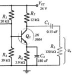
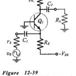
Capacitor Coupled Common Base Amplifier: A practical Capacitor Coupled Common Base Amplifier (using a plus/minus supply) is shown in Fig. 12-39. [Note the polarity of the input coupling capacitor (C1).]…
BIFET Amplifier: BJT-FET Considerations : Two-stage BJT circuits usually have relatively low input impedances. To increase Zi, a field effect transistor may be used as the first stage. Circuits which…
Single Stage Common Source Amplifier: Bias circuit design for the Single Stage Common Source Amplifier in shown in Fig. 12-10. As with the common-emitter BJT circuit, design commences with specification…
Single Stage Common Emitter Amplifier Circuit: Specification - Bias circuit design for the Single Stage Common Emitter Amplifier Circuit in shown in Fig. 12-1 and ac analysis of the circuit…
FET and BJT Difference: FET and BJT Difference (CS, CD, and CG Circuit Comparison) - Table 11-1 compares Zi, Zo and Av for CS, CD, and CG circuits. As already discussed, the…
Common Gate Circuit: The FET Common Gate Circuit (CG) shown in Fig. 11-19 uses voltage divider bias. The ac output is taken from the drain terminal, and an external load…
Common Drain Amplifier Circuit Diagram: The FET Common Drain Amplifier Circuit Diagram shown in Fig. 11-14 has the output voltage developed across the source resistor (RS). The external load (RL)…
Common Source Circuit Analysis: A FET Common Source Circuit Analysis is shown in Fig. 11-Â6. With the capacitors treated as ac short-circuits, the circuit input terminals are the gate and…