Percentage Reactance in Power System:
The Percentage Reactance in Power System of generators, transformers, reactors etc. is usually expressed in percentage reactance to permit rapid short circuit calculations.
The percentage reactance of a circuit is defined as under :
It is the percentage of the total phase-voltage dropped in the circuit when full-load current is flowing.
i.e.,
Where
I = full-load current
V = phase voltage
X = reactance in ohms per phase
Alternatively, percentage reactance (%X) can also be expressed in terms of kVA and kV as under :
where X is the reactance in ohms.
If X is the only reactance element in the circuit, then short-circuit current is given by ;
i.e. short circuit current is obtained by multiplying the full-load current by 100 / % X.
For instance, if the Percentage Reactance in Power System of an element is 20% and the full-load current is 50 A, then short-circuit current will be 50 x 100/20 = 250 A when only that element is in the circuit.
It may be worthwhile to mention here the advantage of using Percentage Reactance in Power System instead of ohmic reactance in short-circuit calculations. Percentage reactance values remain unchanged as they are referred though transformers, unlike ohmic reactances which become multiplied or divided by the square of transformation ratio. This makes the procedure simple and permits quick calculations.
Percentage Reactance and Base WA:
It is clear from exp. (ii) above that percentage reactance of an equipment depends upon its kVA rating. Generally, the various equipments used in the power system have different kVA ratings. Therefore, it is necessary to find the Percentage Reactance in Power System of all the elements on a common kVA rating. This common kVA rating is known as base kVA. The value of this base kVA is quite unimportant and may be :
- equal to that of the largest plant
- equal to the total plant capacity
- any arbitrary value
The conversion can be effected by using the following relation :
Thus, a 1000 kVA transformer with 5% reactance will have a reactance of 10% at 2000 kVA base.
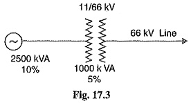
The fact that the value of base kVA does not affect the short circuit current needs illustration. Consider a 3-phase transmission line operating at 66 kV and connected through a 1000 kVA transformer with 5% reactance to a generating station bus-bar. The generator is of 2500 kVA with 10% reactance. The single line diagram of the system is shown in Fig. 17.3. Suppose a short-circuit fault between three phases occurs at the high voltage terminals of transformer. It will be shown that whatever value of base kVA we may choose, the value of short-circuit current will be the same.
(i) Suppose we choose 2500 kVA as the common base kVA. On this base value, the reactances of the various elements in the system will be :
Reactance of transformer at 2500 kVA base
Reactance of generator at 2500 kVA base
Total percentage reactance on the common base kVA
The fullf load current corresponding to 2500 kVA base at 66 kV is given by ;
(ii) Now, suppose we choose 5000 kVA as the common base value.
Reactance of transformer at 5000 kVA base
Reactance of generator at 5000 kVA base
![]() Total percentage reactance on the common base kVA
Total percentage reactance on the common base kVA
![]() Full-load current corresponding to 5000 kVA at 66 kV is
Full-load current corresponding to 5000 kVA at 66 kV is
which is the same as in the previous case.
From the above illustration, it is clear that whatever may be the value of base kVA, short-circuit current is the same: However, in the interest of simplicity, numerically convenient value for the base kVA should be chosen.


