Performance of Single Phase Short Transmission Line Voltage:
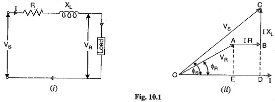
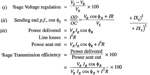
As stated earlier, the effects of line capacitance are neglected for a short transmission line. Therefore, while studying the performance of such a line, only resistance and inductance of the line are taken into account. The equivalent circuit of a Single Phase Short Transmission Line Voltage is shown in Fig. 10.1 (i). Here, the total line resistance and inductance are shown as concentrated or lumped instead of being distributed. The circuit is a simple a.c. series circuit.
Let
I = load current
R = loop resistance i.e., resistance of both conductors
XL = loop reactance
VR = receiving end voltage
cos ΦR = receiving end power factor (lagging)
VS = sending end voltage
cos ΦS = sending end power factor
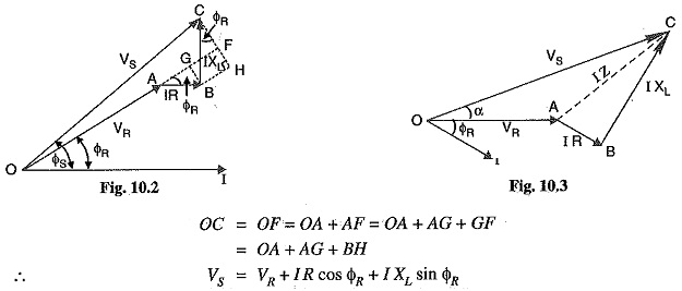
An approximate expression for the sending end voltage VS can be obtained as follows. Draw perpendicular from B and C on OA produced as shown in Fig. 10.2. Then OC is nearly equal to OF i.e.,
Solution in complex notation: It is often convenient and profitable to make the calculations in complex notation.
Taking VR as the reference phasor, draw the phasor diagram as shown in Fig 10.3. It is clear that VS is the phasor sum of VR and I Z
The second term under the root is quite small and can be neglected with reasonable accuracy. Therefore, approximate expression for VS becomes :
The following points may be noted :
- The approximate formula for VS (= VR + I R cos ΦR + I XL sin ΦR) gives fairly correct results for lagging power factors. However, appreciable error is caused for leading power factors. Therefore, approximate expression for VS should be used for lagging p.f. only.
- The solution in complex notation is in more presentable,form.


