Phase Control of Three Phase Induction Motor:
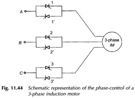
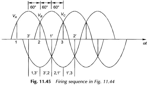
Figure 11.44 shows the schematic representation of Phase Control of Three Phase Induction Motor. Two thyristors are connected in antiparallel in each line. The firing sequence of the thyristors for all modes of operation is 1, 3′, 2, 1′, 3 and 2′ as shown in Fig. 11.45. The interval between successive firings is 60° and the firing frequency is six times the input frequency. It is seen from Fig. 11.45 that as 3′ is fired 1 and 3′ conduct for 60°; then 2 is fired and 3′ and 2 conduct for the next 60° and so on.
Each thyristor after being fired conducts for 120°. As long as a thyristor conducts the corresponding phase voltage will be known. When a phase gets open circuited, its voltage will be that induced due to currents flowing in the other two windings of the motor. As a result of phase control, the effective ac rms voltage applied to motor terminals decreases. This indeed is a method of voltage control.

