Phase Shift in Star Delta Transformer:
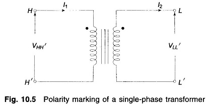
Positive and negative sequence voltages and currents undergo a Phase Shift in Star Delta Transformer which depends upon the labelling of terminals. Before considering this phase shift, we need to discuss the standard polarity marking of a single-phase transformer as shown in Fig. 10.5.
The transformer ends marked with a dot have the same polarity. Therefore, voltage VHH′ is in phase with voltage VLL′. Assuming that the small amount of magnetizing current can be neglected, the primary current I1, entering the dotted end cancels the demagnetizing ampere-turns of the secondary current I2 so that I1 and I2 with directions of flow as indicated in the diagram are in phase. If the direction of I2 is reversed, I1 and I2 will be in phase opposition.
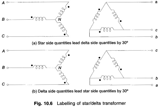
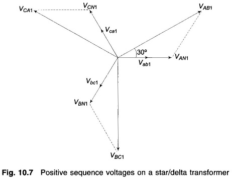
Consider now a star/delta transformer with terminal labelling as indicated in Fig. 10.6 (a). Windings shown parallel to each other are magnetically coupled. Assume that the transformer is excited with positive sequence voltages and carries positive sequence currents. With the polarity marks shown, we can immediately draw the phasor diagram of Fig. 10.7. The following interrelationship between the voltages on the two sides of the transformer is immediately observed from the phasor diagram.
As per Eq. (10.34), the positive sequence line voltages on star side lead the corresponding voltages on the delta side by 30° (The same result would apply to line-to-neutral voltages on the two sides). The same also applies for line currents.
If the delta side is connected as in Fig. 10.6(b) the Phase Shift in Star Delta Transformer reverses (the reader should draw the phasor diagram); the delta side quantities lead the star side quantities by 30°.
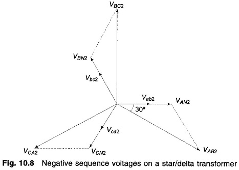
Instead, if the transformer of Fig. 10.6(a) is now excited by negative sequence voltages and currents, the voltage phasor diagram will be as in Fig. 10.8. The Phase Shift in Star Delta Transformer in comparison to the positive sequence case now reverses, i.e., the star side quantities lag the delta side quantities by 30°. The result for Fig. 10.6(b) also correspondingly reverses.
It shall from now onwards be assumed that a star/delta transformer is so labelled that the positive sequence quantities on the HV side lead their corresponding positive sequence quantities on the LV side by 30°. The reverse is the case for negative sequence quantities wherein HV quantities lag the corresponding LV quantities by 30°.


