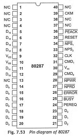
Pin diagram of 80287 co-processor:
The pin diagram of 80287 co-processor is shown in Fig. 7.53 and the function of pins are given below:
D15-D0 The D15-D0 is used as a 16-bit data bus which is connected with the 80286 data bus.
CLK This is a clock input pin though which 80287 co-processor receive the required clock for deriving the system.
RESET The RESET is used to reset 80287 co-processor.
N̅P̅R̅W̅ (Numeric Processor Write) The numeric processor write input pin enables a data transfer from the 80286 main processor to 80287 co-processor.
N̅P̅R̅D̅ (Numeric Processor Read) The numeric processor read active-low input signal is used to enable data transfer from 80287 coprocessor to 80286 main processor.
N̅P̅S̅1 and NPS2 Numeric processor select input pins N̅P̅S̅1 and NPS2 and indicate that the CPU is performing an escape operation. These Pin diagram of 80287 co-processor are also used to enable 80287 co-processor to execute the next instruction.
CMD0 and CMD1 The command pins CMD0 and CMD1 are used to indicate that the CPU is performing an ESC instruction and to control the operations of 80287.
E̅R̅R̅O̅R̅ The error status output signal represents the ES bit of the internal status register. When this pin is active low, it indicates that an exception has occurred.
B̅U̅S̅Y̅ The BUSY output pin indicates to the main processor that 80287 co-processor is busy with the execution of an instruction. This Pin diagram of 80287 co-processor is connected with the TEST pin of 80286.
PEREQ (Processor Extension Request) The processor extension request active HIGH output pin is used to indicate to the 80286 that the 80287 NDP is ready for data transfer.
P̅E̅A̅C̅K̅: (Processor Extension Acknowledge) The processor extension acknowledge active LOW input pin is used by the main processor to acknowledge a receipt of a valid processor extension request signal.
CKM (Clock Mode) When the clock mode input pin, CKM is high, the CLK input is directly used for deriving the internal timings.
