PLC Components:
A PLC is a solid state device designed to perform logic functions previously accomplished by electro-magnetic relays. Basically, the PLC Components is an assembly of solid state digital logic decisions which provides outputs. PLCs are used for the control and operation of manufacturing, process equipment and machinery.
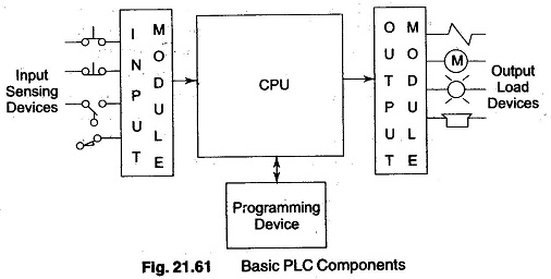
A typical PLC can be divided into three sections as illustrated in Fig. 21.61. These sections are the input/output (I/O) section, Central Processing Unit (CPU) and the programming device.
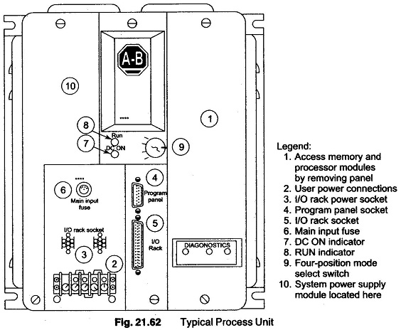
The CPU is the important section of a PLC and is the brain of the system. It contains internally a number of logic gates. The CPU shown in Fig. 21.62 is a microprocessor based system that replaces control relays, counters, timers and sequencers. It is designed so that the user can enter the desired circuits in relay ladder logic. The CPU accepts (reads) input data from various sensing devices, executes the stored user program from memory and sends the appropriate output commands to control devices.
A dc Power source is required to produce dc low level voltage used by the processor and the I/O modules. This power supply can be housed in the CPU unit or may be a separately mounted unit depending on the PLC manufacturer.
The I/O section consists of input modules and output modular. The 1/0 forms the interface by which field devices are connected to the controller. The purpose of this interface is to condition the various signals received from or sent to external field devices. Input devices such as Push Button, limit switches, sensors, selector switches and thumb wheel switches are hard wired to the terminals on the input modules.
Output devices such as small motors, motor starters, solenoid valves and indicator lamps are hard wired to the terminals on the output modules. These devices are referred to as field or real world inputs and outputs.
The terms field or real world are used to distinguish actual external devices that exists and must be physically wired from the internal user program that duplicates the function of relays, timers and counters.
The programming device, or the terminals are used to enter the desired program into the memory of the processor. This program is entered using relay ladder logic. The program determines the sequence of operation and ultimate control of the equipment or machinery. The programming device must be connected to the controller only when entering or monitoring the program. By designing the controller to be “electrician friendly”. The PLC can be programmed by people without extensive computer programming experience. The programming unit may be a hand held unit, a LED display or a desktop unit with a CRT display.

