PLC Hardware:
PLC hardware falls into the following physical configuration:
- Fixed Input/ Output (I/O) and
- Modular I/O.
1.Fixed 1/0 PLCs
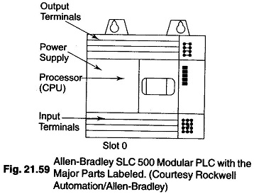
A fixed PLC Hardware consists of a fixed, or built-in, input/output section. There is one fixed or built-in, non removable screw terminal strip containing all input signal screw terminal connections and another terminal strip containing all output control signal screw terminals.
Figure 21.59 shows an Allen Bradley fixed SLC 500 PLC. The plastic door labeled output terminals is hinged at the bottom. On opening the door, all of built-in screw terminals can be seen. The area labeled Input terminals is also a plastic door hinged at the top. On opening the door all the built-in input screw terminals can be seen.
2.Modular I/O PLC
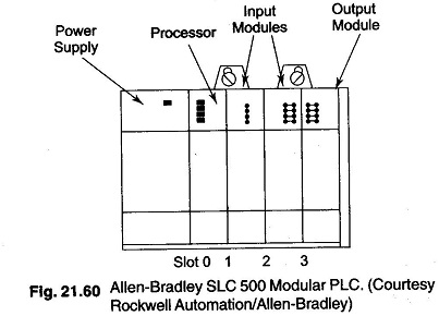
A modular PLC does not have a terminal strip built into the processor unit. Modular PLC have their I/O points on plug-in type, removable units called I/O Modules. PLC Hardware with modular inputs and outputs consist of a chasis, rack or base plate where the power supply, CPU and all input and output modules are present as separate hardware item. The diagram shown in Fig. 21.60 is assembled to make a working PLC.
When I/0 is modular, the user can mix input and output types in the rack or base plate to meet the specific needs. There are usually few limitations on the mix or positioning of I/O modules.
Common racks, chasis or base plates hold 4, 5, 7, 8, 10, 13 or 16 I/O modules. Typical modules will contain 4, 8, 12, 16 or 32 I/0 points. Electrical connections between each modules and CPU are made by two mating plugs.
One plug is located on a printed circuit board at the back of each module. A PCB that the modules plug into runs along the back of the rack or is built into a base plate, called the backplane. The backplane conveys signals from the CPU to each module and from module to the CPU.
A DIN rail is a metal track or rail attached to the back of an electrical panel, where devices can be easily clipped to or removed from the rail. The advantage of the DIN rail is that it permits easy snap-on and removal of hardware devices either at installation or for maintenance or replacement.
The power supply, which is also modular, is hooked up to line voltage. The function of the PLC Hardware power supply is to convert line voltage to low voltage dc and then isolate it for use to operate the CPU and any associated I/O module electronics in the rack or chasis. In most cases power must be supplied to all field input and output devices from a source other than the PLC’s power supply.
The CPU works like a human brain. It is a solid state microprocessor integrated chip, which is placed on PCB with other supporting and interface chips to build the PLC’s CPU or processor module. The CPU basically consists of two components. The controller and memory system.
The controller is the microprocessor or The brain that supervises all operations in the systems. The CPU reads or gathers information from external sources such as the input devices and stores this information in memory for later use by the CPU. When solving the user program is done, the CPU will write or send, data out to the external devices such as output modules and field hardware devices.
The memory system used has to provide the following:
- Storage for the user program.
- Storage of input status file data. The input status file consists of memory locations, that stores the ON-OFF status of each field input
- Storage of output status file data. The output status file consists of memory locations that store ON or OFF status of field hardware devices as the result of solving the user program. Data in the output status file is waiting to be transferred to the output module switching device. This device for each output point will turn power ON or OFF to each field output device.
- Data Storage: The data storage area of the memory is used to store numerical data that may be used in mathematical calculations, bar code data being input to the PLC’s similar function.

