PLC Register:
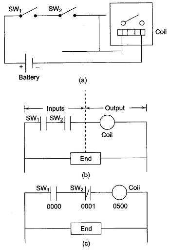
PLC Register – Let us consider a simple example and compare the ladder diagram with its real world external physically connected relay circuit. In Fig. 21.32 (a), the coil circuit will be energized when there is a closed loop between the ‘+’ and ‘—’ terminals of the battery. The same circuit can be drawn using ladder diagram. A ladder diagram consists of individual rungs. Each rung must contain one or more inputs and one or more outputs. The first instruction on a rung must always be an input instruction and last instruction on a rung should always be an output coil. The ladder diagram of Fig. 21.32(a) is shown in Fig. 21.32(b).
The PLC Register in use can be explained by using Fig. 21.32(b) and changing SW2 from normally open to normally closed as shown in Fig. 21.32(c).
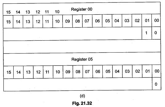
Hence, in Fig. 21.32(c), SW1 will be physically OFF and SW2 will be physically ON initially. Each symbol or instruction has been given an address. This address sets aside a certain storage area in the PLC data files so that the status of the instruction (i.e. true/false) can be stored. Most PLCs uses 16 slots or bit storage locations. In the example given above, two different storage locations or PLC Register are used.
In the tables of two registers 00 and 05 shown in Fig. 21.32(d), we can see that in register 00, bit 00 corresponding to input 0000 was a logic 0 and bit 01 corresponding to input 0001 was a logic 1. Register 05 shows that bit 00 corresponding to output 0500 was a logic 0. The logic 0 or 1 indicate whether an instruction is False or True.
The PLC will only energise an output when all conditions on the rung are TRUE. Hence, in the above example, SW1 must be logic 1 and SW2 must be logic 0, then and only then the output (coil) will be True, that is energized.
If any instruction on the rung before the output (coil) is false, then the output (coil) will be false (not energized).

