Polarised Relay:
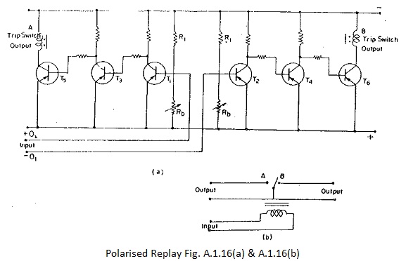
This Polarised Relay is very frequently employed where operation is required in two directions. In a d.c. Polarised Relay contact A is closed when current in the operating winding flows in one direction contact B will be closed if the current direction reverses as shown in Fig. A.1.16(b). An exactly similar operation can be obtained with the help of a transistorised circuit, shown in Fig. A.1.16(a).
This circuit contains six transistors as shown with input terminals O1 and O2. When current flows from O1 to O2 i.e. O1 positive and O2 negative, transistor T1 is ON and T2 is OFF. T1 in the ON condition switches T3 OFF and T3 ON so that there will be flow of current through transistor T5 (load transistor) and contacts in the relay A are closed as its coil is energised. When the direction of current is reversed such that O1 is negative and O2 is positive, transistor T1 is OFF and T2 is ON thereby switching T6 to ON condition. This energises relay B which closes its contacts. When there is no input current at O1-O2, both relays A and B are dc-energised and their contacts are open. This is equivalent to the polarised relay having its contact floating between points A and B of Fig. A.l.16(b).
Static and Electromechanical Equivalents
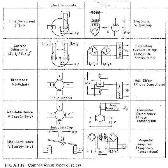
Fig. A.1.17 shows the basic static equivalents of electromagnetic or electromechanical relays. This is only a preliminary type of comparison and greater details will be found in the succeeding chapters. The comparison shows time-over current, current-differential, reactance and Mho-admittance types of relays and the reader can assess the circuit equivalence by himself before he reads the details in the relevant chapters for each case.
Device Numbers and Functions
Each device in an automatic switching equipment has a device function number which is placed adjacent to or within the device symbol on all wiring diagrams and arrangement drawings so that its function and operation may be readily identified. These numbers are based on a system which is adopted internationally.
