Polyphase Circuits Articles:
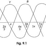
Polyphase System: In an ac system it is possible to connect two or more number of individual circuits to a common polyphase source. Though it is possible to have any number of sources in a polyphase system, the increase in the … (Read More)
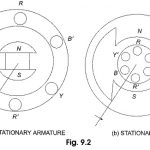
Generation of Three Phase Voltage: Three Phase Voltage can be generated in a stationary armature with a rotating field structure, or in a rotating armature with a stationary field as shown in Fig. 9.2 (a and b). Single phase voltages and currents … (Read More)
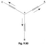
Inter Connection of Three Phase Source and Loads: Inter Connection of Three Phase Source and Loads consists of for Parts, Namely Inter Connection of Three Phase Source Wye or Star-Connection Delta or Mesh-connection Interconnection of Loads (a) Inter Connection of Three Phase Source: In a three-phase alternator, … (Read More)
Star Delta Transformation Formula: While dealing with currents and voltages in loads, it is often necessary to convert a Star Delta Transformation Formula, and vice-versa. It has already been seen that delta (Δ) connection of resistances can be replaced by an … (Read More)
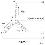
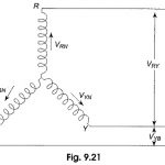
Voltage, Current and Power in 3 Phase Star Connection: 3 Phase Star Connection – Figure 9.21 shows a balanced three-phase, Y-connected system. The voltage induced in each winding is called the phase voltage (Vph). Likewise VRN, VYN and VBN represent the rms values … (Read More)
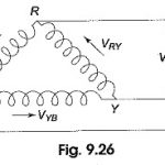
3 Phase Delta Connection: Delta Connected System – Figure 9.26 shows a balanced three-phase, three-wire, delta-connected system. This arrangement is referred to as mesh connection because it forms a closed circuit. It is also known as 3 Phase Delta Connection because … (Read More)
Three Phase Balanced Circuit: The analysis of Three Phase Balanced Circuit is presented in this section. It is no way different from the analysis of AC systems in general. The relation between voltages, currents and power in delta-connected and star-connected systems … (Read More)
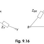
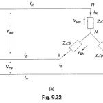
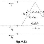
Unbalanced Three Phase Circuit Analysis: Types of Unbalanced Loads – An unbalance exists in a circuit when the impedances in one or more phases differ from the impedances of the other phases. In such a case, line or phase currents are … (Read More)
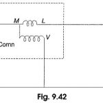
Power Measurement in Single Phase Circuit by Wattmeter: Wattmeters are generally used to measure power in the circuits. A wattmeter principally consists of two coils, one coil is called the current coil, and the other the pressure or voltage coil. A … (Read More)
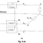
Power in Three Phase Circuits: Measurement of power by a wattmeter in a single phase circuit can be extended to measure Power in Three Phase Circuits. From earlier Section, it is clear that we require three wattmeters, one in each phase … (Read More)
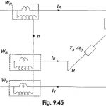
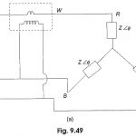
Three Wattmeter and Two Wattmeter Method: In this method, the three wattmeter are connected in the three lines as shown in Fig. 9.45, i.e. the current coils of the three wattmeter are introduced in the three lines, and one terminal of … (Read More)
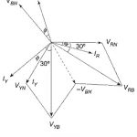
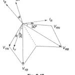
Power Factor by Two Wattmeter Method: When we talk about the power factor in three-phase circuits, it applies only to balanced circuits, since the power factor in a balanced load is the power factor of any phase. We cannot strictly define … (Read More)
Leading Power Factor Load: Suppose the load in Fig. 9.46(a) is capacitive, the wattmeter connected in the leading phase would read less value. In that case, WR will be the lower reading wattmeter, and WY will be the higher reading wattmeter. … (Read More)
Reactive Power with Wattmeter: We have already seen earlier that the difference between higher reading wattmeter and lower reading wattmeter yields VLIL sin Φ. So, the total reactive power = √3 VLIL sin Φ. Reactive Power with Wattmeter in a balanced … (Read More)
Effects of Harmonics: The relationship between line and phase quantities for wye and delta connections as derived earlier are strictly valid only if the source voltage is purely sinusoidal. Such a waveform is an ideal one. Modern alternations are designed to … (Read More)
