Precision Rectifiers:
Recall from basic circuit principles that a rectifier circuits can be implemented with a diode/diodes (half wave rectifier or full wave rectifier). The major limitations of these Precision Rectifiers circuits is that they cannot rectify voltages below VD(ON) = 0.7 V, the cut-in voltage of the diode. In these circuits Vi has to rise to a threshold of the order of VD(ON) before any appreciable change can be seen at the output.
Therefore, above this threshold we have Vo = Vi – VD(ON) ≈ Vi – 0.7 V and below threshold Vo = 0V i.e.
Due to this, output of the conventional rectifier is distorted.
To achieve Precision Rectifiers we need a circuit that keeps Vo equal to Vi for Vi>0V. This can be achieved by using op-amp along with the diodes and these circuits are called Precision Rectifiers. These are used to precisely rectify voltages having amplitudes less than 0.7V.
Precision Half Wave Rectifiers:
There are two types of precision half wave rectifiers available,
- Noninverting half wave rectifier
- Inverting half wave rectifier
Noninverting Half Wave Rectifier:
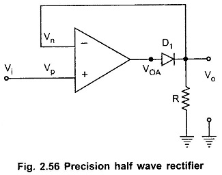
Fig. 2.56 shows precision half wave rectifier. It consists of noninverting amplifier with diode D1 in the feedback loop of an op-amp.
The analysis of this circuit can be done considering two distinct case Vi > 0 V and Vi < 0 V.
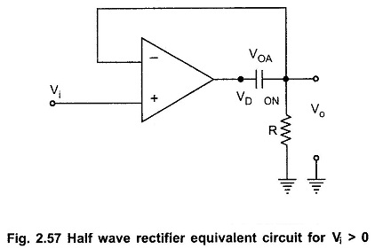
CASE 1 : Vi > 0 V : Recall that for closed loop op-amp Vp = Vn, due to virtual ground.
When Vi > 0, op-amp tries to keep Vo = Vn = Vp = Vi and it does this because forward biasing diode provides closed loop feedback path. The voltage drop across forward bias diode VD(ON) = 0.7 V.
To accommodate the voltage drop across diode the op-amp swings about 0.7V higher than Vo, as shown in the Fig. 2.57.
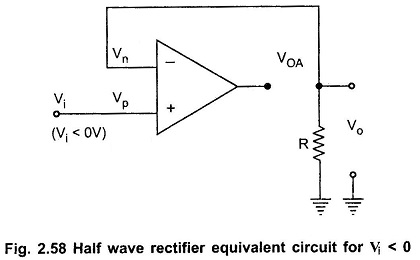
CASE 2 : Vi < 0V : When Vi < 0V, diode D1 is reverse biased and the op-amp is working in the open loop, as shown in the Fig. 2.58.
Therefore, op-amp is no longer capable of keeping Vn = Vp.
With no current through resistance R we have Vo = 0.
the op-amp output VoA is saturated at Vsat-.
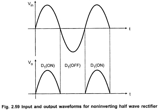
The input and output waveforms are shown in Fig. 2.59.
Inverting Half Wave Rectifier:
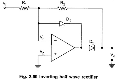
Fig. 2.60 shows another popular circuit, inverting half-wave rectifier. It consists of two diodes and two resistors and op-amp is connected in the inverting configuration.
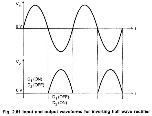
CASE 1: Vi > 0 : Recalling virtual ground concept we can say that Vp = Vn = 0V. For Vi > 0, Vi is positive with respect to Vn and hence current through R1 flows from left to right. Only one path for this current to flow is through diode D1. Hence diode D1 is forward biased and diode D2 is reverse biased. As current flow through R2 is zero, Vo = Vn = 0V.
CASE 2 : Vi < 0 : For Vi < 0, Vi is negative with respect to Vn and hence current through R1 flows from right to left. Only one path for this current to flow is through diode D2 and resistor R2, indicating that VoA > Vn. Hence diode D1 is OFF, and diode D2 is ON. With these diode states, circuit acts like an inverting amplifier and output voltage is given as
If R1 and R2 are made equal, then we can write Vo = -Vi
The input and output waveforms are shown in Fig. 2.61.

